Sling angle is routinely treated as a marginal technical detail on the job site, something that gets a glance, not a calculation. Yet OSHA Standard 29 CFR 1910.184 (Slings) explicitly identifies neglecting the lifting angle as one of the primary contributing factors in industrial lifting configuration failures.
A sling rated at 5-ton WLL can lose half its working capacity from angle alone — with zero physical damage to the equipment itself.
This is not speculation. It is a mathematical consequence that can be calculated before the crane moves a single centimeter.
The problem is that sling angle rarely receives the same attention as sling type selection or WLL verification. Even experienced riggers sometimes estimate the lifting angle by eye rather than by calculation — and visual estimation is consistently wrong, especially as the angle approaches 30° from horizontal.
This article covers how to calculate it: formula, reference table, and a field measurement method that requires nothing more than a tape measure.
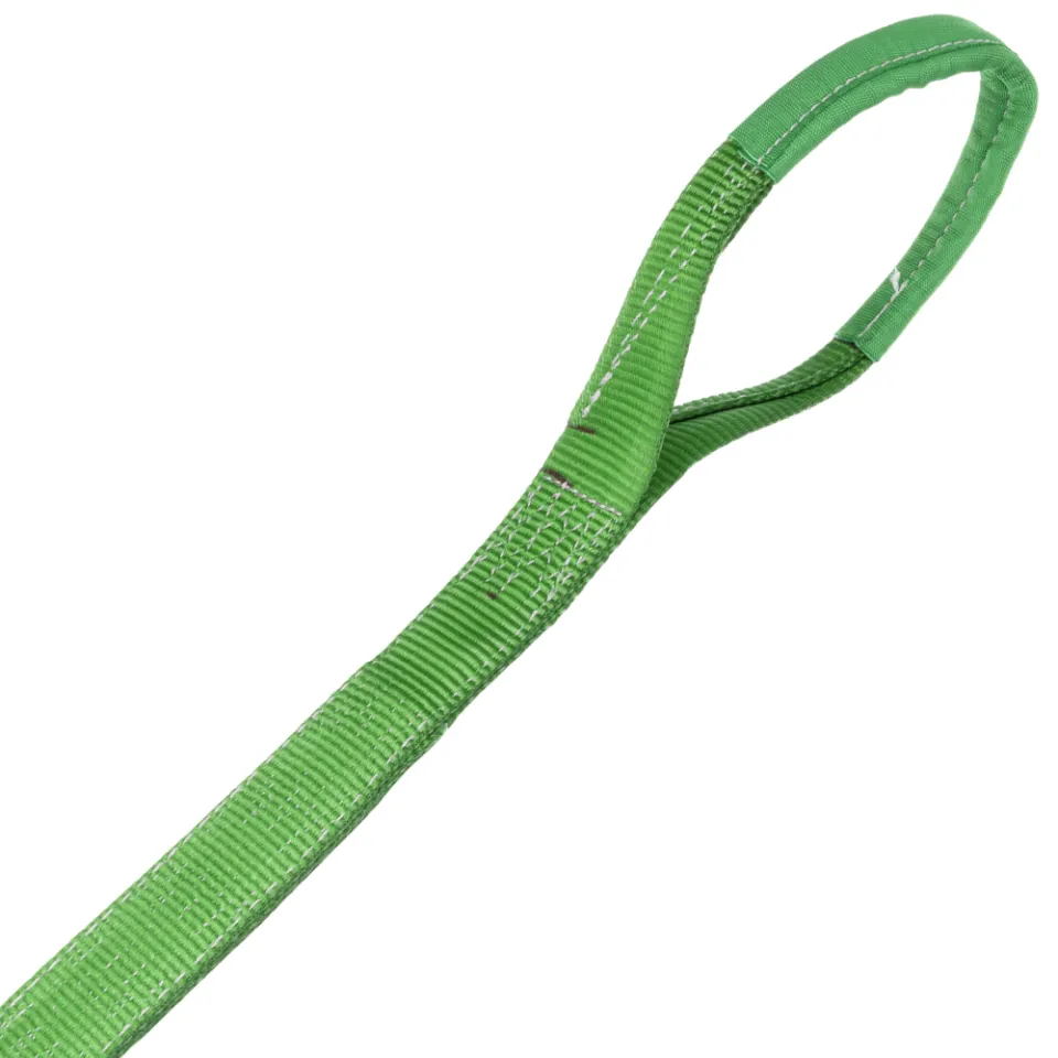
Webbing Sling SpanSet


What Is Sling Angle?
The sling angle is the angle formed between a sling leg and the horizontal plane during a lifting operation. The smaller that angle (i.e., the closer to horizontal the sling runs), the greater the tension each leg must bear — which directly reduces the effective WLL that is safe for the operation.
A sling leg working at a shallow angle behaves like the rafters of an ancient pitched roof: the more gradual the slope, the greater the outward thrust the supporting walls must resist. Structures collapse not from the load pressing down from above, but from the horizontal component that was never accounted for. Sling angle follows exactly the same logic.
International standards including EN 1492-1 (synthetic webbing slings) and ASME B30.9 explicitly define the minimum permitted lifting angle in rigging operations. This is not administrative formality — it is technical protection grounded in vector physics.

Calculating Sling Angle: Formula and Step-by-Step
The following is the standard field format for a two-leg bridle, based on the methodology in J. Keith Anderson's Rigging Engineering Basics.
n — Number of sling legs actively bearing the load
θ (Theta) — Angle between the sling leg and the horizontal plane
(1 ÷ sin θ) — Tension factor; increases as θ decreases
To determine the effective WLL of a sling at a given angle:
- Load per leg before angle correction: 10 ÷ 2 = 5 tons
- Tension factor at 45°: 1 ÷ sin 45° = 1 ÷ 0.707 = 1.414
- Actual tension per leg: 5 × 1.414 = 7.07 tons
Round Sling SpanSet


Sling Angle Reference Table: 90° to 20°
The table below summarizes the tension factor and effective WLL at each common sling angle, expressed as a percentage of nominal WLL.
| Sling Angle (θ) | sin θ | Tension Factor (1/sin θ) | Effective WLL (%) |
|---|---|---|---|
| 90° | 1,000 | 1,00 | 100% |
| 75° | 0,966 | 1,04 | 96,6% |
| 60° | 0,866 | 1,15 | 86,6% |
| 45° | 0,707 | 1,41 | 70,7% |
| 30° | 0,500 | 2,00 | 50,0% |
| 20° | 0,342 | 2,92 | 34,2% |
At 60°, a sling still operates at 86.6% of nominal capacity — an adequate margin for most standard operations. At 30°, that capacity collapses to 50%. Half the WLL is lost due to angle alone. Anything at 20° or below falls into the high-risk category and is generally prohibited by international safety standards.
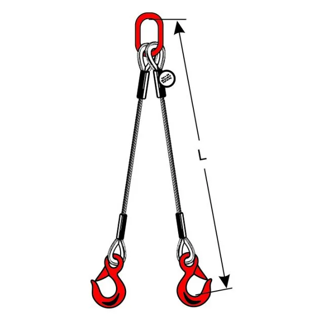
Two-Leg Bridle vs. Four-Leg Sling Load Distribution
On a two-leg bridle, a decreasing sling angle increases tension per leg cleanly and predictably per the formula above — provided both legs are equal length and the lift point sits directly above the load's center of gravity.
Why Four-Leg Slings Don't Always Distribute Load Evenly
In field practice, four-leg slings almost never distribute load equally across all four legs. Minor surface irregularities, microscopic variations in leg length, or a slightly shifted hook position are enough to cause two legs to carry the majority of the load while the other two are nearly unloaded.
This is why common industry practice recommends calculating a four-leg sling's capacity as equivalent to three active legs, to account for this inherent imbalance.
When sling angle decreases at the same time, the effects stack: an already uneven load must also absorb additional tension from a non-ideal angle. The combination is where the real risk lives.
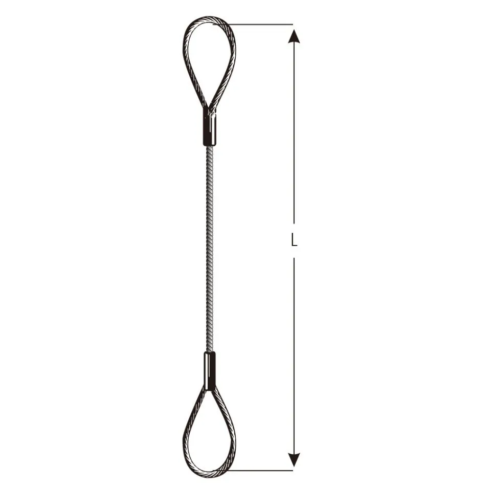
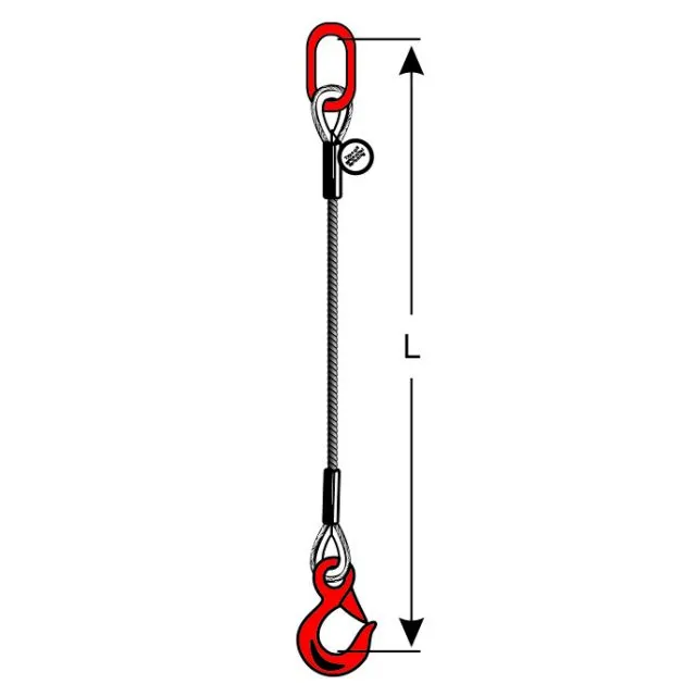
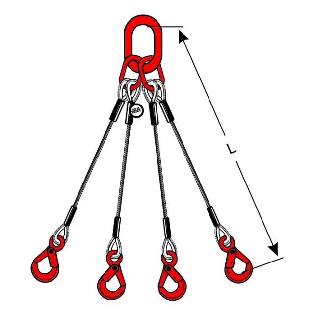
Wire Rope Slings SpanSet
How to Measure Sling Angle in the Field — No Protractor Required
The h/d ratio method allows riggers to determine sling angle using only a tape measure. It is accurate enough for rapid field decisions before a lift begins.
- Measure h — the vertical distance from the lifting point (hook) down to the sling attachment point on the load.
- Measure d — half the horizontal distance between the two sling attachment points (for a two-leg bridle).
- Compare the ratio:
· If h = d → angle ≈ 45°
· If h = 1.73 × d → angle ≈ 60°
· If h = 0.58 × d → angle ≈ 30°
Key principle: The larger h is relative to d, the more vertical the sling leg — and the safer the operation.
This method does not replace formal calculation, but it reliably detects dangerous conditions before lifting work begins.
International Safety Standards Governing Minimum Sling Angle
|
ASME B30.9
Clause 9-1.5.3
Explicitly prohibits the use of horizontal lifting angles below 30°. Mandates a minimum safety factor of 5:1 against breaking load. |
EN 1492-1
Synthetic Webbing Slings
Specifies usage coefficient tables based on lifting angle and requires a minimum safety factor of 7:1 against breaking load. |
Hazards from equipment used outside its rated lifting angle include premature sling damage, hook failure, and unpredictable load drops. Periodic equipment inspections must include verification that all rigging configurations respect permitted sling angle ranges — not just a visual check of the sling's physical condition. Documentation of lifting angles used in each operation is part of responsible work records.
Sling Protection


Common Sling Angle Estimation Mistakes and How to Avoid Them
Mistake 1
"45° is still safe — it's above the 30° limit."
At 45°, the effective WLL has already dropped 30% from nominal capacity. That is not a margin that can be ignored, especially under variable load conditions.
Mistake 2
"A longer sling automatically improves the lifting angle."
The lifting angle is determined by the geometry of the hook point and the spread distance — not by sling length. Substituting a longer sling without relocating the spread points produces negligible improvement in the angle.
Damage signature:
Overloading from a shallow angle typically appears as deformation at the sling end stitching, not as tears in the sling body itself. This damage is easily missed in an untrained visual inspection.
A single angle estimation error rarely causes immediate failure — but repeated operations below the safe threshold significantly accelerates material degradation.
FAQ: Pertanyaan yang Sering Muncul soal Sling Angle
Q: What is the minimum safe sling angle according to international standards?
ASME B30.9 Clause 9-1.5.3 explicitly prohibits lifting angles below 30° from horizontal. EN 1492-1 reinforces this through usage coefficient tables showing a sharp WLL drop below that angle. At 30°, the tension factor reaches 2.0 and safety margins become too thin for standard operations.
Q: Does sling angle apply equally to synthetic slings and wire rope?
Yes. The tension factor formula applies to all sling types — webbing slings, round slings, and wire rope slings. The difference lies in the nominal WLL of each type, not in how lifting angle affects working capacity.
Q: How can I quickly check sling angle in the field without an angle gauge?
Use the h/d ratio method: measure the vertical height from the hook to the sling attachment point (h), and half the horizontal distance between the two attachment points (d). If h is less than d, the angle is already below 45° and further calculation is required before the lift begins.
Q: Does sling angle affect four-leg slings?
Yes — and more critically. On four-leg slings, load distribution is almost never perfectly even in practice. The combination of uneven distribution and a shallow sling angle can cause one or two legs to bear loads far exceeding their nominal WLL, with no visible indication of the problem.